
Mission-Critical Control Room Display Planning
An engineering manual covering operator sightline geometry, heat load calculation, IP video wall decoding bandwidth, electrical loop redundancy, and ISO 11064 ergonomic standards.
The Five Pillars of Mission-Critical Visualization
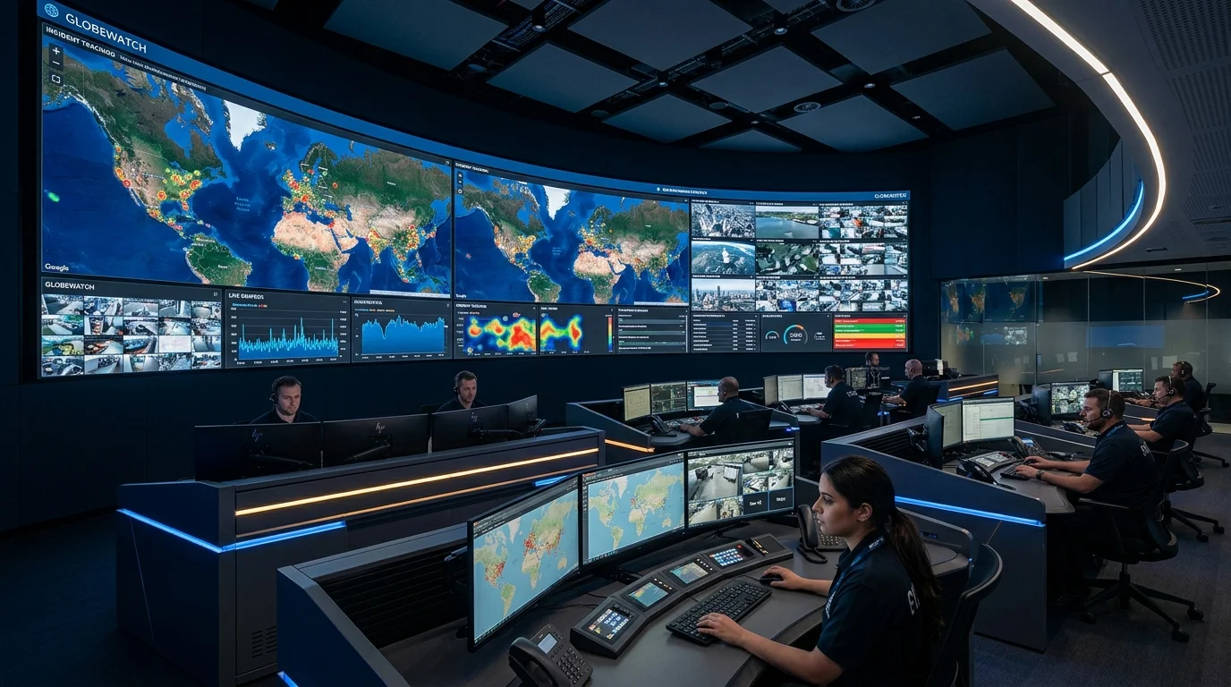
Unlike commercial signage or corporate presentation screens, a command and control room video wall operates under severe operational constraints. It must remain active 24 hours a day, 365 days a year, displaying mission-critical telemetry, live security surveillance, and emergency maps without unexpected failures.
Designing a world-class Operations Center (NOC, SOC, EOC) requires compliance with ISO 11064 (Ergonomic Design of Control Centres) and rigorous engineering across five key disciplines:
- Sightline Geometry & Ergonomics: Ensuring all operators have unobstructed views without cervical neck strain.
- Thermal Dissipation & Acoustics: Removing heat quietly without high-RPM fans disturbing critical communications.
- Electrical & Signal Redundancy: Dual-feed power loops and redundant IP video pathways.
- Processor Video Decoding Bandwidth: Low-latency hardware multi-windowing supporting dozens of concurrent 4K RTSP streams.
- Sub-Millimeter Front Serviceability: Replacing faulty components in under 60 seconds without disrupting adjacent channels.
Control Room Engineering Checklist
Core engineering disciplines required during the architectural design phase.
1. ISO 11064 Sightline Geometry
Maximum vertical gaze angle must not exceed 30° from the operator's relaxed eye level to the top edge of the video wall. Horizontal viewing angles across the furthest console workstations should remain within ±45° of display center.
2. Thermal Load & HVAC Sizing
Calculate heat output using: BTU/hr = Total Watts × 3.412142. Fine-pitch LED walls run cooler with common-cathode power supplies, typically generating 180–250 Watts/m² at calibrated 300 nits control room brightness.
3. Dual Electrical & Loop Redundancy
Specify dual AC input feeds from independent UPS circuits. Connect LED cabinet sender-receiver signal loops in a closed ring; if any ethernet cable or intermediate receiver fails, the backup return loop takes over in <10 milliseconds.
Control Room Video Processing Benchmarks
Comparing dedicated hardware video processors vs. software-based workstations.
| System Attribute | FPGA Dedicated Hardware Processor | PC / OS-Based Software Server |
|---|---|---|
| Boot Time & Recovery | Under 5 seconds (Pure FPGA hardware) | 60 – 180 seconds (Windows/Linux OS boot) |
| Vulnerability to Blue-Screen / Virus | Zero vulnerability (No commercial OS layer) | Subject to OS patches, crashes, and malware |
| Concurrent IP Stream Decoding | Hardware DSP decoding up to 64x 1080p or 16x 4K | CPU/GPU bottlenecks under high stream density |
| Processing Latency | Ultra-low <20 milliseconds | 100 – 300 milliseconds software buffering |
| Switching Speed | Instantaneous frame-accurate crossfade | Noticeable black screen or buffering pauses |